01
GEOMETRY
WALL THICKNESS
Wall thickness is the most fundamental DfAM parameter. Too thin and walls won't bond correctly, collapse mid-print, or be structurally useless. Too thick and you waste material, extend print time, and risk warping from thermal mass. Every process has different physics — know your process first.
| PROCESS | ABSOLUTE MIN | RECOMMENDED | FUNCTIONAL / STRUCTURAL | NOTES |
|---|---|---|---|---|
| FFF / FDM | 0.8 mm | 1.2 – 3.0 mm | ≥ 2.0 mm | Must be multiples of nozzle Ø (0.4 mm nozzle → 0.8, 1.2, 1.6 mm) |
| SLA / RESIN | 0.4 mm | 0.8 – 2.0 mm | ≥ 1.5 mm | Thin vertical walls fine; large flat thin faces warp during cure |
| SLS / PA12 | 0.7 mm | 1.0 – 3.0 mm | ≥ 1.5 mm | No supports; thin walls cool unevenly and may warp |
| METAL LPBF | 0.3 mm | 1.0 – 1.5 mm | 2 - 6.0 mm | Machining stock needed on critical surfaces; thermal distortion present |
| FGF / PELLET | 1.5 mm | 2.0 – 6.0 mm | ≥ 4.0 mm | Nozzle Ø typically 1–3 mm; ideal for large structural components |
FFF RULE
Wall = N × Nozzle Diameter
Design walls as exact multiples of nozzle diameter. Partial-width walls generate weak toolpaths and unpredictable extrusion behaviour.
0.4 mm → 0.8, 1.2, 1.6 mm
STRUCTURAL
Functional Components
Load-bearing parts should use at least 2 mm wall thickness and multiple perimeter walls for optimal strength.
≥ 2.0 mm
AVOID
Thin Pins & Features
Features below 1 mm diameter become fragile, inaccurate, or may be ignored entirely by slicers.
≥ 1 mm Diameter
Garuda3D Tip
Use perimeter count rather than absolute wall thickness wherever possible. Three perimeter walls typically outperform a single thick wall while improving dimensional consistency and print reliability.
02
GEOMETRY
OVERHANGS & SUPPORTS
Overhangs are surfaces that extend beyond the layer below without support. FFF and SLA are gravity-constrained — molten or liquid material sags without support. SLS is self-supporting because unsintered powder holds the part. Designing to minimise supports reduces cost, print time, and surface scarring on functional faces.
| ANGLE (FROM VERTICAL) | FFF RESULT | SUPPORT NEEDED? | STRATEGY |
|---|---|---|---|
| 0° – 45° | Clean, no issues | No | Design all critical overhangs within this zone |
| 45° – 60° | Minor sagging, rough underside | Sometimes | Add chamfer to steepen the angle; test first |
| 60° – 89° | Significant sag, surface failure | Yes | Redesign with chamfer, or accept support post-processing |
| 90° (BRIDGE) | Possible up to ~60 mm span | Depends on span | Keep bridge ≤ 60 mm; cool fast and print slow |
Overhang angle guide for FFF / FDM processes — angles measured from vertical axis
✓ DESIGN TO
- Use 45° chamfers instead of horizontal shelves
- Teardrop-profile holes on vertical walls (self-supporting)
- Orient the part so critical surfaces face up or vertical
- Keep bridges under 60 mm; reduce layer height for bridges
- Use soluble PVA supports for SLA — zero surface scarring
- Request tree/organic supports for complex SLA geometries
✕ AVOID
- Horizontal overhangs wider than 60 mm without supports
- Support contact on cosmetic or functional mating surfaces
- Sharp 90° corners on overhanging edges — they curl
- Assuming support removal leaves zero surface artefacts
- Designing internal cavities you can't extract supports from
30°
GOOD
Self-supporting geometry with excellent print reliability.
45°
RECOMMENDED
Industry standard design limit for FFF printing.
60°
SUPPORTS NEEDED
Surface quality begins to degrade without support.
90°
AVOID
High risk of sagging and print failure.
03
PRINT SETTINGS
LAYER HEIGHT & RESOLUTION
Layer height controls surface finish, Z-direction mechanical strength, and print time. Lower layers bond better and produce smoother finishes, but extend runtime and cost. The rule: layer height must not exceed 75–80% of nozzle diameter for reliable inter-layer bonding in FFF.
| TIER | LAYER HEIGHT (FFF) | SURFACE QUALITY | Z-STRENGTH | TIME MULTIPLIER | IDEAL USE |
|---|---|---|---|---|---|
| Draft | 0.3 – 0.4 mm | Rough — visible steps | Moderate | 1× (fastest) | Fit/form checks, concept models |
| Standard | 0.15 – 0.25 mm | Moderate — faint lines | Good | 2× | Functional prototypes, jigs, fixtures |
| Fine | 0.08 – 0.12 mm | Fine — subtle lines | Very good | 4–5× | Housings, presentation models |
| Ultra (SLA) | 0.025 – 0.05 mm | Near-smooth | Excellent | 8–10× | Dental, jewellery, micro-features |
| FGF / Pellet | 0.5 – 2.0 mm | Industrial — defined layers | High (volume) | — | Large structural / industrial parts |
Critical Rule
For FFF, layer height must not exceed 75–80% of nozzle diameter. A 0.4 mm nozzle: max 0.32 mm layer height. Exceeding this causes insufficient squish-overlap, dramatically reducing inter-layer bonding strength.
04 DIMENSIONAL
TOLERANCES & FIT
3D printing is not precision machining. All processes have dimensional variation — the question is how much and where. Design assemblies with this variation in mind. For any assembly-critical feature, always print and test a tolerance coupon before committing to a production run.
| PROCESS | TYPICAL TOLERANCE | BEST ACHIEVABLE | XY VS Z | NOTE |
|---|---|---|---|---|
| FFF / FDM | ± 0.2 – 0.5 mm | ± 0.1 mm | XY better | Calibrated machines; thermal shrinkage varies by material |
| SLA / Resin | ± 0.1 – 0.2 mm | ± 0.05 mm | XY best | Excellent for small parts; large flat faces warp |
| SLS / PA12 | ± 0.2 – 0.3 mm | ± 0.1 mm | Isotropic | Very consistent; good for assemblies without post-processing |
| Metal LPBF | ± 0.05 – 0.2 mm | ± 0.02 mm (machined) | Variable | Thermal distortion common; critical holes should be finish-machined |
| MJF (HP) | ± 0.2 – 0.3 mm | ± 0.1 mm | Isotropic | Best for snap-fits and living hinges |
MOVING PARTS / CLEARANCE FIT
Sliding & Rotating
Add 0.3 – 0.5 mm gap per side for FFF parts that move relative to each other. Test before finalising.
Gap: 0.3 – 0.5 mm / side
PRESS FIT
Interference / Shrink
Design holes 0.1 – 0.2 mm smaller than shaft. FFF holes are slightly oval — always test one first.
Hole: shaft Ø − 0.1 mm
ENCLOSURES / LIDS
Assembly Fit
Snap-on lids or enclosures: 0.1 – 0.2 mm total gap. FFF vertical walls shrink slightly — test first print before scaling.
Total gap: 0.1 – 0.2 mm
THREADED HOLES
Heat-Set Inserts
For brass heat-set inserts, match hole OD exactly to insert OD. For self-tapping screws, design +0.2 mm oversize.
Self-tap: +0.2 mm OS
Best Practice
Always print a tolerance test coupon — matched boss and hole pair — in the target material on the target machine before printing a full assembly. Offsets between machines, materials, and ambient temperature are significant and not accounted for in nominal specs.
05 MATERIAL
SELECTION
MATERIAL SELECTION BY APPLICATION
Material choice determines mechanical performance, temperature resistance, chemical compatibility, and post-processing options. The wrong material in the right geometry still fails. Match material properties to your application's actual demands — not just availability or cost.
| IF YOUR PART NEEDS… | CONSIDER THIS MATERIAL | PROCESS |
|---|---|---|
| High stiffness, low weight | Carbon Fibre-Filled Nylon, PEEK, CF-PLA | FFF |
| Flexibility / elasticity | TPU (Shore A 87–95), TPE | FFF / SLS |
| High temperature resistance (>150°C) | PEEK, PEI (Ultem), PA-CF | FFF |
| Food-safe / medical contact | PETG (food grade), PA11 (bio-based), biocompatible resins | FFF / SLA |
| UV / outdoor stability | ASA, UV-stable PETG, PA12 (post-treated) | FFF / SLS |
| Complex geometry, no supports | PA12, PA11, TPU powder | SLS |
| Investment casting patterns | Castable resin (zero-ash burnout) | SLA |
| Corrosion-resistant metal | 316L Stainless Steel | Metal LPBF |
| High strength-to-weight metal | Ti-6Al-4V, AlSi10Mg | Metal LPBF |
| Large industrial prototypes (cost-effective) | ABS pellets, PP pellets, recycled polymers | FGF |
PLA
Easy to Print, Low Warp
Biodegradable (industrial)
HDT ~55°C
Prototypes · Display Models · Education
ABS
Impact Resistant, Machineable
Warp-prone — needs enclosure
HDT ~95°C
Enclosures · Automotive · Functional Parts
PETG
Good Chemical Resistance
Food-grade options available
HDT ~70°C
Medical · Food Contact · Containers
NYLON (PA)
High Toughness, Low Friction
Hygroscopic — must dry before print
HDT ~110°C
Gears · Bearings · Living Hinges
TPU
Flexible, Abrasion Resistant
Shore A 87–95
HDT ~60°C
Gaskets · Grips · Wearables
CF-NYLON / CF-PLA
High Stiffness, Lightweight
Requires hardened nozzle
HDT ~115°C
Jigs · Fixtures · Drone Frames
ASA
UV Stable, ABS-Like Toughness
Outdoor use rated
HDT ~95°C
Outdoor Signage · Automotive Exterior
PEEK / PEI
Chemical Resistant
Needs 400°C+ nozzle
HDT ~250°C
Aerospace · Medical · Oil & Gas
STANDARD
General Purpose Resin
Smooth finish, high detail
Models · Prototypes
TOUGH
ABS-Like Resin
Impact resistant
Functional Parts
FLEXIBLE
Elastic Resin
Rubber-like properties
Gaskets · Wearables
PA12
General Engineering Nylon
Strong and durable
Functional Assemblies
PA11
Impact Resistant
High ductility
Snap Fits
TPU
Flexible Powder
Elastic and durable
Seals · Grips
316L
Stainless Steel
Corrosion resistant
Industrial Parts
Ti64
Titanium
High strength-to-weight
Aerospace · Medical
INCONEL
High Temperature Alloy
Extreme heat resistance
Turbines · Aerospace
06
BUILD STRATEGY
PART ORIENTATION
Orientation affects strength, surface quality, dimensional accuracy, support generation, and print time. The same part printed in a different orientation can have dramatically different performance characteristics. Always orient the part for its primary load path rather than appearance alone.
| ORIENTATION GOAL | RECOMMENDED STRATEGY | BENEFIT |
|---|---|---|
| Maximum Tensile Strength | Align load path in XY plane | Strongest layer bonding |
| Best Surface Finish | Critical faces upward or vertical | Reduced support scars |
| Dimensional Accuracy | Orient precision features in XY | Better tolerance control |
| Minimum Supports | Use self-supporting geometry | Reduced print time and post-processing |
| Fastest Build | Reduce Z-height | Lower layer count |
❌ Flat Orientation
- More support material
- Longer print time
- Rough underside finish
- Higher material consumption
→
✅ Optimised Orientation
- Reduced supports
- Improved surface quality
- Lower material usage
- Faster printing
STRENGTH
XY > Z
FFF parts are anisotropic. Strength in the XY plane is typically 40–60% greater than strength across layer boundaries.
Load In XY
SURFACE QUALITY
Hide Supports
Orient cosmetic faces away from support structures whenever possible. Support removal always leaves some surface witness marks.
Reduce Scarring
PRINT TIME
Reduce Height
Lower Z-height means fewer layers and significantly shorter production time.
Faster Builds
| GOAL | ORIENTATION STRATEGY |
|---|---|
| Minimise Supports | Rotate until overhangs are steeper than 45°. A 10–15° tilt often eliminates large support structures entirely. |
| Circular Holes / Bores | Orient so holes lie in the XY plane — they print as true circles. Holes in Z print as stepped cylinders needing post-drilling. |
| Round / Cylindrical Features | Print cylindrical axes vertical for smoothest curves. Horizontal cylinders show layer stacking on curved surfaces. |
| Anisotropic Strength (Known Load) | Layer interfaces should be perpendicular to the load direction. Parallel interfaces fail at 40–60% the in-plane strength. |
| Minimum Print Time | Orient to minimise part height in Z — print time scales with total Z layers, not XY footprint. |
07
SLICER SETTINGS
INFILL & WALL COUNT
Infill is the internal lattice of an FFF/FDM print. Combined with wall (perimeter) count, it controls strength, weight, and print time. Most parts do not need 100% infill — and increasing wall count improves strength more efficiently than increasing infill density.
| INFILL % | WEIGHT / TIME | STRENGTH | BEST APPLICATION |
|---|---|---|---|
| 5 – 15% | Very light / Fast | Surface supported only | Display models, non-structural shapes |
| 20 – 35% | Light / Medium | General purpose | Housings, enclosures, fit-check prototypes |
| 35 – 60% | Medium / Moderate | Good mechanical | Functional parts, jigs, fixtures |
| 60 – 80% | Heavy / Slow | High impact resistance | Structural brackets, load-bearing parts |
| 100% | Heaviest / Slowest | Maximum (often unnecessary) | Press-fit zones, small threaded features, grinding surfaces |
BEST ALL-ROUND PATTERN
GYROID
Isotropic — equal strength in all 3 directions. Best for parts with unknown or multi-directional loads. Self-supporting structure.
Recommended Default
SPEED-OPTIMISED
GRID / LINES
Fast to print. Weaker in one axis. Suitable for non-critical internals where print speed is the priority.
Fastest Print Time
MINIMUM WEIGHT
LIGHTNING
Minimal structure — just enough to support top surfaces. Ideal for display models and aesthetic parts where mass is undesirable.
Lightest Option
Key Principle
Walls Beat Infill
4 perimeter walls + 20% infill is structurally stronger than 2 walls + 60% infill. Walls carry load; infill mainly prevents surface collapse.
≥ 3 walls for load parts
08 Geometry
Feature Design Rules
Small features — holes, bosses, text, slots, threads — have minimum printable dimensions that vary by process. Features below these limits will either be omitted by the slicer, merge into adjacent surfaces, or print inaccurately. Design with these constraints explicitly in mind.
| Feature | FFF Min | SLA Min | SLS Min | Notes |
|---|---|---|---|---|
| Hole (vertical axis) | 2.0 mm Ø | 0.5 mm Ø | 1.5 mm Ø | Design +0.2 mm oversize in FFF to hit nominal after shrinkage |
| Hole (horizontal axis) | 3.0 mm Ø | 1.0 mm Ø | 2.0 mm Ø | Use teardrop profile for FFF — top of hole is self-supporting |
| Embossed text | 1.0 mm high / 0.6 mm deep | 0.3 mm | 0.8 mm | Engraved text prints cleaner than raised text in FFF |
| Standalone pin / boss | 1.0 mm Ø | 0.3 mm Ø | 0.8 mm Ø | Height > 3× diameter — add gusset or taper |
| Internal threads | M3 minimum | M2 minimum | M3 minimum | Below M3 in FFF: use brass heat-set inserts instead |
| Slot / channel width | 1.0 mm | 0.3 mm | 0.8 mm | Closed channels in SLS trap powder — add clearance holes for evacuation |
| Gap between mating surfaces | 0.3 mm min | 0.2 mm min | 0.5 mm min | SLS: unfused powder can fuse small gaps — always leave ≥ 0.5 mm |
| Chamfer / fillet radius | 0.4 mm min | 0.2 mm min | 0.4 mm min | Chamfers on all sharp external edges reduce stress concentration and improve bonding |
Sharp Corners
Chamfer or fillet all sharp external corners on printed parts — especially on FFF. Shrinking forces concentrate at sharp points, causing delamination and crack initiation under load. A 0.5 mm chamfer adds no print cost and significantly increases fatigue resistance.
09
Process Rules
Technology-Specific Design Rules
DfAM rules differ significantly between technologies. What is acceptable in SLS will fail in FFF. What is fine in SLA needs different treatment in Metal AM. Select your process below and design to its specific constraints — not to a generic set of rules.
FDM / FFF
Fused Deposition / Fused Filament Fabrication
- Wall Minimum wall 0.8 mm; design as multiples of nozzle diameter (0.4 mm nozzle → 0.8, 1.2, 1.6 mm). Use ≥ 3 perimeters for structural parts.
- Overhang Self-supporting up to 45° from vertical. Add chamfers or reduce angles beyond 45°. Bridges under 60 mm span print without support.
- Support Supports leave surface marks — never place them on cosmetic faces, sealing surfaces, or thread features. Specify where support contact is not acceptable.
- Warping Large flat parts on ABS, Nylon, and PC warp at corners. Add brim, use enclosure, and fillet base corners. Avoid large flat sections >150 mm in one direction without ribs.
- Orientation Layer interfaces run perpendicular to Z — parts are weakest in Z tension. Orient so primary tensile loads run in XY. Anisotropy is 40–60% weaker in Z.
- Threads Internal threads below M3 fail — use brass heat-set inserts (press in post-print with soldering iron).
SLA / Resin
Stereolithography / Photopolymer Resin
- Drain Holes Hollow SLA parts trap uncured resin. Add at least two drain holes (≥ 3 mm Ø) on non-visible faces — one to drain, one to vent. Without these, trapped resin expands and cracks the part.
- Wall Minimum 0.4 mm vertical walls; 0.8 mm recommended for functional parts. Large thin flat sections.
- Supports SLA supports are thinner than FFF and leave smaller witness marks, but are still present. Orient parts to minimise supports on cosmetic or mating surfaces. Request tree supports for complex parts.
- Resin Traps Concave upward-facing pockets trap resin between layers and create suction forces that delaminate the part. Orient parts to avoid upward-facing cups, or add small drainage holes.
- Surface SLA produces the smoothest surfaces of all AM processes. Top-facing surfaces are smoother than bottom-facing (support-side). Orient cosmetic faces upward for best finish.
- Post-Cure UV post-curing adds 0.1–0.2 mm shrinkage on small features. Measure critical dimensions after curing, not before. Design dimensional-critical features 0.15 mm oversized.
- Detail SLA can print features as small as 0.3 mm. However, sharp thin protrusions (pins, blades) under 0.5 mm are fragile — add a fillet at the base for durability.
SLS / Powder
Selective Laser Sintering — PA12, PA11, TPU Powder
- No Supports SLS is fully self-supporting — unsintered powder surrounds the part. This enables complex undercuts, internal channels, and interlocking assemblies impossible in FFF.
- Powder Escape Hollow parts and closed channels trap unsintered powder. Add escape holes (≥ 5 mm Ø) to evacuate powder after printing. Without escape holes, powder is permanently locked inside.
- Wall Minimum 0.7 mm; recommended 1.0 mm+. Very thin walls (under 0.8 mm) cool unevenly and warp. Uniform wall thickness avoids differential cooling stresses.
- Gaps Small gaps
- Nesting SLS allows nesting multiple parts in the same build volume with no spatial separation required. Design parts for dense nesting to reduce per-part cost.
- Surface SLS produces a matte, slightly grainy surface. Bead blasting improves tactile quality. Dyeing, painting, and clear-coating are all compatible with PA12 and PA11.
- Isotropy SLS PA12 is nearly isotropic (equal properties in all directions). Unlike FFF, there is no need to orient the part for Z-axis strength — design freely.
Metal AM
Laser Powder Bed Fusion — Stainless, Titanium, Aluminium, Inconel
- Thermal Distortion Metal AM builds under significant thermal stress. Overhangs and horizontal surfaces distort if unsupported. Design all metal AM overhangs below 45° or add support structures.
- Support Strategy Metal AM supports must be machined or ground off — they leave a rough witness surface. Place supports only on non-functional surfaces.
- Residual Stress Rapid solidification creates residual stress that causes warping and cracking. Stress relief heat treatment is mandatory for most metal AM parts.
- Machining Stock Add 0.3–0.5 mm machining stock on all critical surfaces (bores, mating faces, threads, sealing surfaces).
- Wall Minimum 0.3 mm; recommended 0.5 mm+ for structural features. Walls under 0.4 mm have inconsistent microstructure and reduced fatigue strength.
- Powder Evacuation Internal channels and hollow structures trap metal powder. Add escape holes (≥ 3 mm Ø).
- Build Direction Build parts with the largest cross-section at the base to reduce support structures. Critical surface finish should be oriented vertically rather than horizontally.
10
Troubleshooting
Common Design Mistakes
These are the most frequently recurring DfAM errors Garuda3D engineers see in submitted files. Each one causes print failures, dimensional errors, or parts that technically print but fail in use. Recognise these patterns — and their fixes — before your file arrives.
Walls Too Thin
Walls under 0.8 mm in FFF are either skipped by the slicer or print as single-line extrusions with no structural integrity. Common on imported CAD from injection moulding designs.
Thicken all walls to minimum 1.2 mm for FFF. Use the slicer
preview to check for red/missing wall warnings before sending
the file.
Sharp Internal Corners
Sharp 90° internal corners concentrate stress and initiate cracks under load. They also cause print artifacts in FFF as the nozzle slows and over-extrudes at the corner.
Fillet all internal corners with minimum 1.0 mm radius.
Larger fillets (2–3 mm) distribute stress better and print
more cleanly at speed.
Unsupported Overhangs
Horizontal surfaces greater than 60 mm span or steeper than 45° will sag, curl, or fail entirely in FFF without supports. Often missed on bottom-facing features.
Add 45° chamfers to convert overhangs to self-supporting
angles. Or specify which surfaces require support and which
cannot have support witness marks.
Enclosed Hollow Cavities
Fully enclosed hollow cavities trap support material in FFF, uncured resin in SLA, and powder in SLS/Metal AM.
Always add drain/access holes (≥ 3 mm Ø) to hollow sections.
For FFF, design as open shells.
Incorrect Tolerances for Assemblies
Designing mating parts with zero clearance leads to press fits in parts designed for clearance fits.
Add 0.3–0.5 mm clearance per side for moving fits. Print a
tolerance test coupon first.
Large Flat Surfaces Causing Warping
Large flat bottom surfaces (>100 mm) on ABS, Nylon, and PC lift at the corners due to thermal contraction.
Add ribs, use a brim, chamfer edges, and consider PETG or PLA
for flat-dominant geometries.
Ignoring Build Direction for Strength
Designing a bracket with the load direction parallel to Z results in a part that fails at 40–60% of the designed load.
Orient the part so tensile loads run through the XY plane.
Consider SLS or Metal AM for isotropic properties.
Threads Below M3 in FFF
FFF threads below M3 don't print reliably and strip under torque.
Use brass heat-set inserts for M3 and below. For M4+, print
holes slightly undersize and tap after printing.
11
Intermediate DfAM
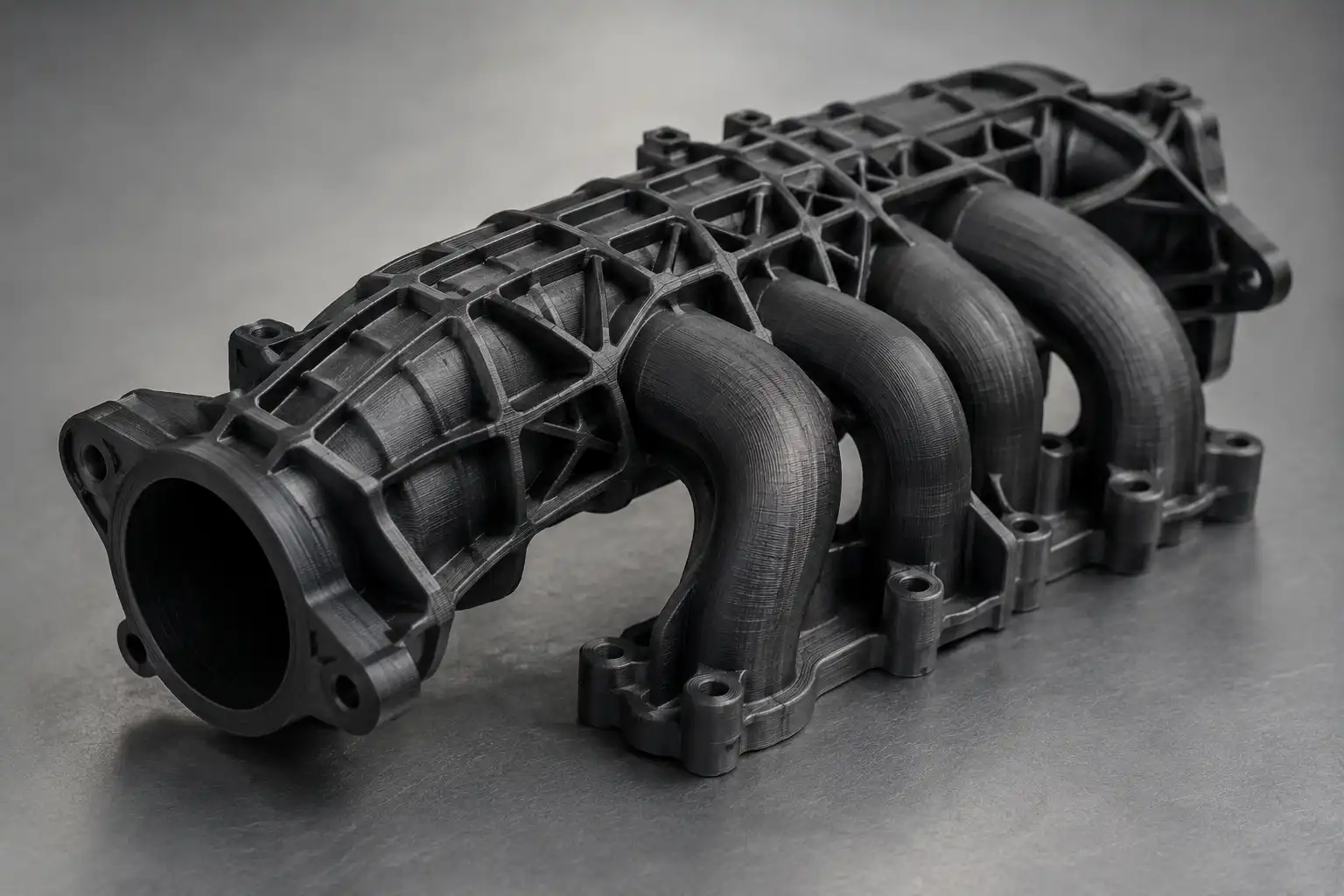
Part Consolidation
One of 3D printing's most powerful advantages over traditional manufacturing: parts that would previously require separate machining, assembly, and fastening can be redesigned and printed as a single component. This eliminates assembly time, reduces failure points, cuts fastener inventory, and often improves structural integrity.
8
Individual Machined Components
Body + bracket + 3 fasteners + spacer + seal + housing — each requiring sourcing, inspection, and assembly time.
→
1
Consolidated 3D-Printed Part
Single print captures all geometry, integrated channels, and mounting features. 40–70% cost reduction is typical.
Opportunity
Bracket + Body
Separate structural brackets bolted to housings are a primary consolidation target — print as one integrated part with built-in gussets.
Opportunity
Internal Channels
Coolant, pneumatic, or cable routing channels that would require external tubing in machined assemblies can be printed directly inside a consolidated body.
Opportunity
Hinge + Body
Living hinges, snap-fit lids, and integrated clips can be printed in-place without assembly — common in PA, TPU, and MJF parts.
Caution
Over-Consolidation
Not all assemblies should be consolidated. Parts that require different materials, need field replacement, or have different end-of-life paths should remain separable.
Indian Manufacturing Context
Part consolidation is particularly valuable for Indian manufacturers dealing with complex supply chains and long lead times on machined components. A single 3D-printed part delivered in 24 hours replaces an 8-part assembly with a 3-week procurement cycle.
12
Advanced DfAM
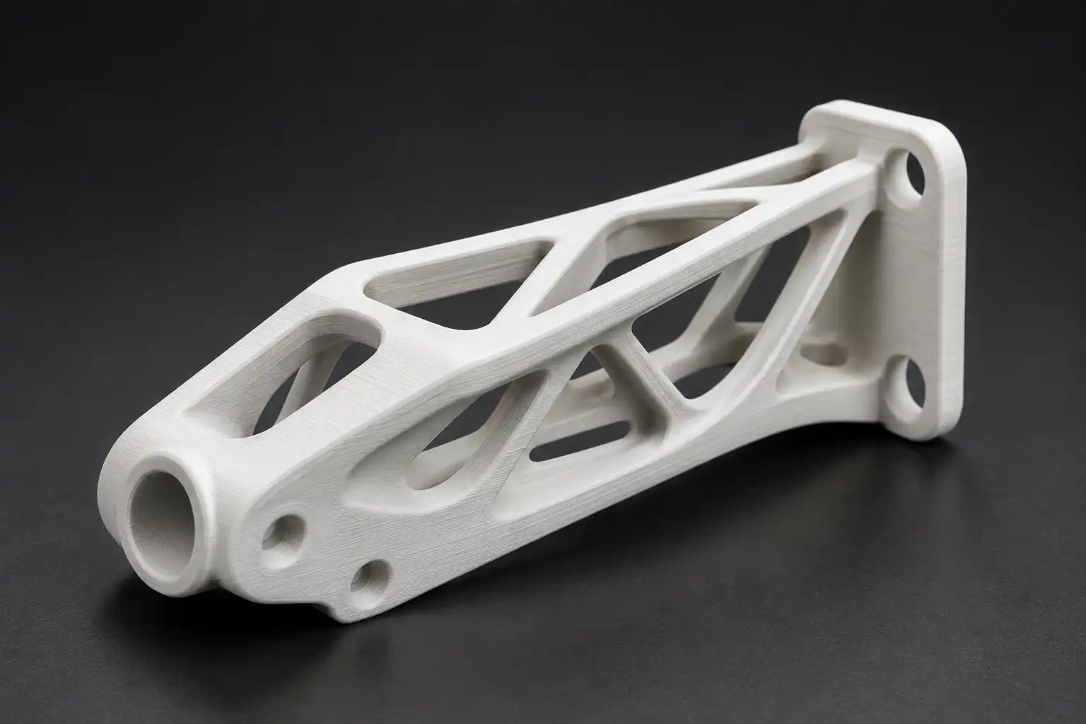
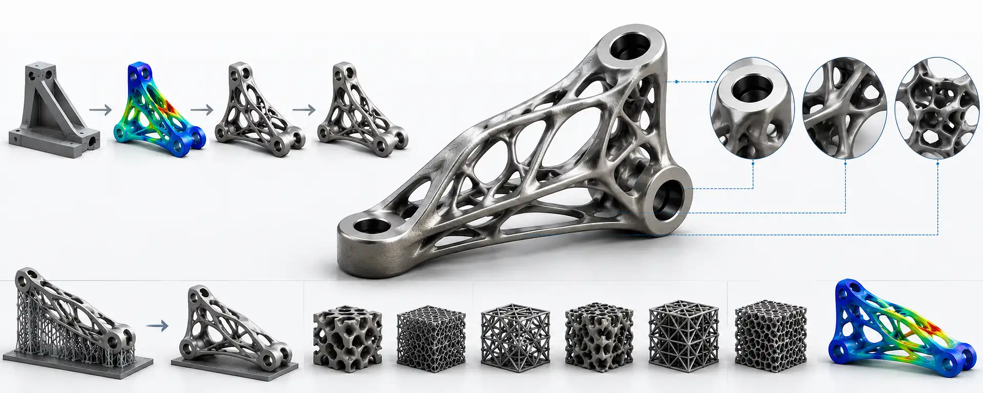
Topology Optimisation & Generative Design
Topology optimisation uses simulation to remove non-load-bearing material from a design while maintaining performance requirements — strength, stiffness, or deflection limits. The result is a part that is simultaneously lighter, stiffer, and often only manufacturable by additive methods due to its organic geometry.
TRADITIONAL DESIGN
Weight: 450 g
Part Count: 6
↓
TOPOLOGY OPTIMISED
Weight: 180 g
Part Count: 1
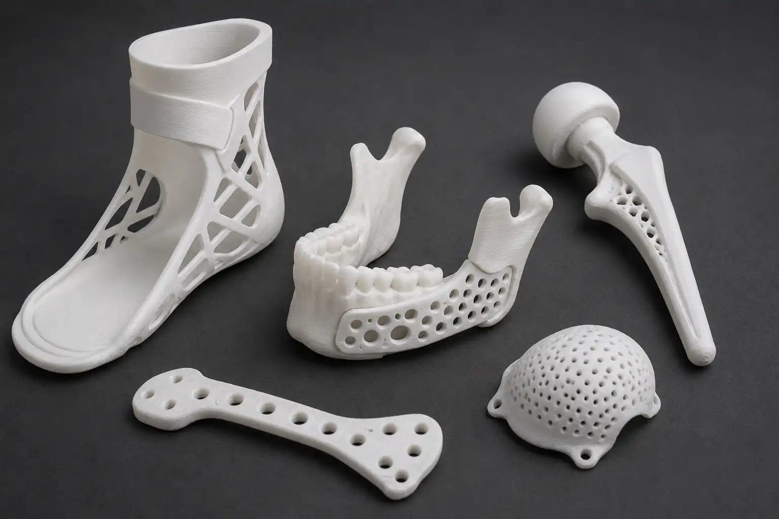
Lattice Structures
Replace solid infill with engineered lattice geometries — gyroid, TPMS, octet truss — to achieve target stiffness at minimum weight. Common in aerospace brackets and orthopaedic implants.
Topology Optimisation
Define load cases and design space. Software (Altair OptiStruct, Siemens NX AM, nTOP, ANSYS) removes material where stress is lowest. Results typically require 30–70% less material than solid designs.
Generative Design
AI-assisted design exploration that generates multiple optimised geometries for a given set of performance constraints and manufacturing method. Best results when AM is specified as the process from the start.Generative design software such as fusion 360, ansys, nTOP, Altair works etc.
| Advanced Technique | What it enables | Typical benefit | Tools |
|---|---|---|---|
| Topology Optimisation | Remove non-structural material based on FEA load paths | 30–70% weight reduction | Altair, ANSYS, Fusion 360, NX |
| Lattice Infill | Replace solid internal structure with engineered lattice | 40–80% weight reduction vs solid | nTop, Materialise Magics, Cura |
| Conformal Cooling | Internal cooling channels that follow part geometry exactly | 30–50% faster cycle times in tooling | nTop, SolidWorks, Creo |
| Generative Design | AI generates multiple optimised geometry options | Explores design space faster | Fusion 360, Creo, NX |
| Graded Density Lattice | Dense lattice at stress zones, light lattice elsewhere | Best performance-to-weight | nTop, Synera |
Garuda3D Note
Topology-optimised geometry and lattice structures are most effective with FFF, SLS, metal LPBF, or pellet FGF processes — where the printer follows geometry rather than being constrained by toolpaths. If you have a topology-optimised STL, our engineers can review it for printability and recommend the right Garuda3D process.
13
Real-World Examples
DfAM in Practice
DfAM is not theory — it delivers measurable results. These examples show what happens when parts are redesigned specifically for additive manufacturing. Weight drops. Part count drops. Lead time drops. Performance improves.
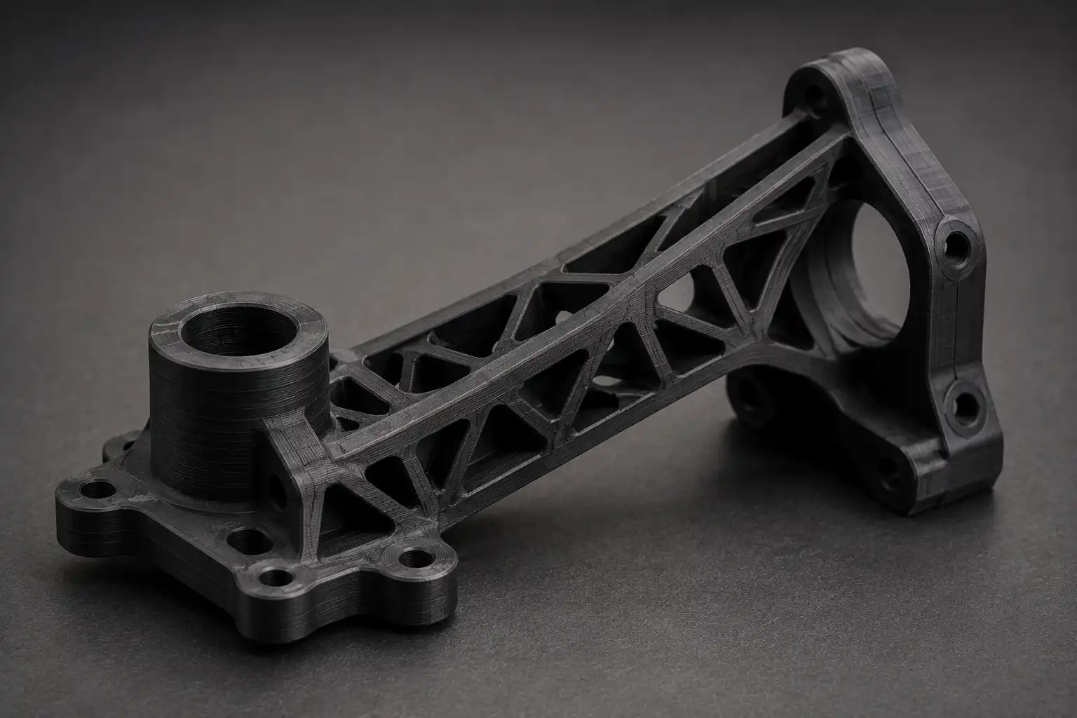
Aerospace Bracket
Structural mounting bracket — Titanium LPBF
Part weight
450 g → 180 g
Part count
6 parts → 1 part
Assembly time
2.5 hours → 0 hours
Lead time
6 weeks → 4 days
60% weight reduction · Topology optimised
Robotic End Effector
Gripper assembly — Carbon Fibre Nylon FFF
Component count
12 machined parts → 1 printed part
Fasteners required
18 fasteners → 0 fasteners
Unit cost
₹18,500 → ₹4,200
Iteration cycle
3 weeks → 48 hours
Part consolidation · 12→1 · 77% cost reduction
Medical Device Housing
Diagnostic enclosure — Biocompatible SLA
Prototype cycle
3 weeks (injection mould) → 2 days
Tooling cost
₹2.8 L (mould) → ₹0
Design iterations
2 (tooling limited) → 7 (cost-free)
Time to clinical trial
5 months → 6 weeks
93% faster prototyping · Zero tooling cost
Have a Part to Optimise?
Garuda3D engineers can review your existing design and identify consolidation opportunities, weight reduction potential, and process recommendations — at no charge during the quoting process. Contact us at info@garuda3d.com.
14
Finishing
Post-Processing Considerations
Post-processing adds time, cost, and dimensional change. Design with the intended finish state in mind — don't add post-processing as an afterthought. Every finishing step must be called out before printing, as it changes the dimensional allowances and material choice.
| Process | Dimensional Impact | Surface Effect | Design Consideration |
|---|---|---|---|
| Sanding / Polishing | −0.2 – 0.5 mm per surface | Removes layer lines; improves Ra | Leave stock; avoid sanding tight-fit features |
| Primer + Paint | +0.1 – 0.3 mm per coat | Fills micro-texture; colour match | Reduce clearances by paint thickness before printing |
| Tapping / Thread | +0.1 – 0.3 mm hole oversize | None | Design holes 10–15% undersize of tap; drill first to true the hole |
| Acetone Vapour (ABS) | −0.2 – 0.5 mm outer wall | Fully smooth surface | Avoid on dimensional-critical or press-fit features |
| UV Post-Cure (SLA) | −0.1 – 0.2 mm shrinkage | Improved hardness, colour stability | Measure critical dims after curing, not before |
| HIP (Metal AM) | 0.1 – 0.3% dimensional change | None | Add machining stock on all critical metal AM surfaces |
| Bead Blast (SLS) | Negligible | Uniform matte, improved tactile | Rounds sharp edges; spec edge tolerance accordingly |
| Heat-Set Inserts | None if pre-designed | None | Match hole Ø exactly to insert OD spec; design boss wall ≥ 2× insert Ø |
15
Ready to Print
Pre-Print Checklist
Every file submitted to Garuda3D goes through this checklist before productiton. Run through it on your end first — files that arrive pre-checked print faster, with fewer revision rounds and lower final cost.
01
Watertight STL or STEP File
No open surfaces, zero-thickness faces, or reversed normals. Use Meshmixer, Netfabb, or PrusaSlicer's repair function before sending.
02
Wall Thickness Checked for Chosen Process
All walls ≥ minimum for the process (FFF: 0.8 mm min, recommended 1.2 mm+). Thin walls visible in slicer preview before printing.
03
Overhangs Within Process Limits or Supports Specified
Overhangs ≤ 45° for FFF. If supports are needed, flag which surfaces cannot have support contact marks.
04
Material Fully Specified (Grade, Colour, Certifications)
Don't leave material open. Specify exact material, colour if required, and any certifications: food-safe, biocompatible, UV-stable, fire-retardant.
05
Assembly-Critical Tolerances Called Out
Identify which dimensions are clearance fits, press fits, or running fits. Include nominal + tolerance, not just nominal. Attach a tolerance coupon if quantities are large.
06
Threads Use Inserts or are M3 or Larger
Internal threads below M3 in FFF should be heat-set brass inserts. Specify thread standard (metric ISO preferred). Note if thread is through or blind.
07
Preferred Orientation Specified
If a specific face requires best finish, or if load direction is known, call it out. Attach a marked diagram or note preferred Z-up axis.
08
Post-Processing Requirements Noted Upfront
Painting, sanding, tapping, insert installation, bead blasting, plating — all affect final dimensions and must be agreed before print, not after.
09
Part Consolidation Opportunities Reviewed
If this part is part of a larger assembly, consider whether 2–5 components can be consolidated. Garuda3D engineers can advise during quoting.
10
Quantity, Delivery Timeline, and Quality Level Confirmed
1–10 parts: standard prototyping. 10–100: pre-production run. 100+: discuss pellet FGF or SLS for cost efficiency. State if functional testing is required.